
(04-03-2017, 01:27 PM)Super Wrote: You are a Wizard Ripley.
...
I take it Super could be the Keeper of Keys and Grounds at BluePlasticTracks.
(04-03-2017, 01:27 PM)Super Wrote: You are a Wizard Ripley. ... I take it Super could be the Keeper of Keys and Grounds at BluePlasticTracks.
So the resistor looks to be yellow,orange, brown, silver, right? It should be 430ohms, i think it's in series with the motor, I can only imagine it's to slow the speed of the motor. if it's in series with the power circuit it's the only thing it can do,
(This post was last modified: 04-04-2017, 12:58 PM by Tramp.)
the transistor thing in the other picture is a capacitor, it's used for smoothing the power spike when the motor is switched on and off, it also suppresses noise and interference that can effect the electronic circuits, on the other engines (with no circuit boards) you can run without it no problems, but with these having the boards it would be worth keeping them. 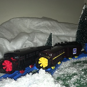
(04-04-2017, 11:54 AM)Tramp Wrote: So the resistor looks to be yellow,orange, brown, silver, right? It should be 430ohms, i think it's in series with the motor, I can only imagine it's to slow the speed of the motor. if it's in series with the power circuit it's the only thing it can do, Do you think if I leave the capacitor and remove the resistors from the (+) and (-) it may Speed the engine up a bit without causing damage to the board?? I ran into another issue with one of the Thomas repairs. Apparently the board had been soldered too much and the bit that the solder attaches to on the board hole is gone. So nothing metal there for the solder to latch onto. I think that one is pretty well shot. I attached the positive wire that goes to the motor over to the speaker (+) and it works now but has issues with the activation/talking when going over track. 
I'm not sure, If it wasn't required I'd have thought that Trackmaster wouldn't have fitted it in the first place, how does the talk and action work? Does it start and stop independently? If it runs by itself it may be that the transistor that controls the switching on and off has a current rating, if you remove the resistor it might consume more current and overwhelm the transistor,
like I said I don't understand why it has the resistor on in the first place, are you sure it is part of the power circuit? Could it be the point where the circuit board takes the power from the main circuit? Obviously the sound circuitboard will require a regulated supply, this might be supplied through the resistor, As for the circuit board with the copper track, if you follow the etched track work back you should be able to find the other end where a component is soldered to it, if your careful you should be able to solder your wire onto the same connection - not pretty but it should work.
(04-06-2017, 09:19 PM)Tramp Wrote: I'm not sure, If it wasn't required I'd have thought that Trackmaster wouldn't have fitted it in the first place, how does the talk and action work? Does it start and stop independently? If it runs by itself it may be that the transistor that controls the switching on and off has a current rating, if you remove the resistor it might consume more current and overwhelm the transistor, So the two wires from the tender which one is negative and the other positive but attached to the middle prong on the 3 prong switch. From there those go directly into the circuit board. Seems like that would be the full 4.5 v (3 x AA). The motor has a (+) and (-) coming off the board which both go to a resistor on each side then the motor. My thought on the capacitor is it is storing a bit of power as some of the track causes a burst in speed, so that may make sense. It does start and stop on its own when going over the track. The acivation mechinisim has two wires that go to the board. One of the terminals that the wires connects to also has the switch wire connected there too. I am working on a wiring diagram that I will try and post here. As a test while I had this one out of the motor chassis I remove the resistors and connected the wires directly to the terminals. It does seem a bit faster now, but hard to tell since this one is not fully assembled yet. I may try this with one of the others to see if it makes a difference. ![[Image: 948_FFED1-2306-4845-87_EC-_F518710_A813_...zbs4mi.jpg]](https://s26.postimg.cc/uwv4mzq55/948_FFED1-2306-4845-87_EC-_F518710_A813_E_zpszmzbs4mi.jpg)
Dang...that last bit of conversation was some serious mad scientist dialogue!!! You guys really amaze me. :O
Play nice & have fun!!

Right then, as far as I can see if the power is 4.5v the resistors will be dropping the voltage down to a suitable level, as you know most of our trains run off of 1.5v, I imagine the resistors will drop the bolts to a similar level, not only will it reduce the volts, it will increase the resistance in the motor circuit. The transistor on the circuit board will be a black three pronged device, this acts as a switch to control the power on to the motor, these transistors can't handle much current, I imagine by increasing the resistance you reduce the amount of current the transistor has to deal with, if you remove the resistors yes I'm sure it will run faster but I don't know how long the transistor will last! The capacitor in the motor is part of the transistor protection as well as noise suppression, as I said before the capacitor acts as a buffer in the power circuit, it charges up then if the motor starts to struggle it discharges assisting this power supply, it just helps to maintain the motor. Also because it works as balance it helps when power is switched on and off on the transistor, it's job will be to buffer the transistor switch by prevebting a voltage spike when the transistor switches off - in industrial applications they would be used to suppress sparks on contact tips,
As for bursts of speed, I'm not sure, Do all the talk & action engine nes do this?
(04-07-2017, 11:08 PM)Tramp Wrote: Right then, as far as I can see if the power is 4.5v the resistors will be dropping the voltage down to a suitable level, as you know most of our trains run off of 1.5v, I imagine the resistors will drop the bolts to a similar level, not only will it reduce the volts, it will increase the resistance in the motor circuit. The transistor on the circuit board will be a black three pronged device, this acts as a switch to control the power on to the motor, these transistors can't handle much current, I imagine by increasing the resistance you reduce the amount of current the transistor has to deal with, if you remove the resistors yes I'm sure it will run faster but I don't know how long the transistor will last! The capacitor in the motor is part of the transistor protection as well as noise suppression, as I said before the capacitor acts as a buffer in the power circuit, it charges up then if the motor starts to struggle it discharges assisting this power supply, it just helps to maintain the motor. Also because it works as balance it helps when power is switched on and off on the transistor, it's job will be to buffer the transistor switch by prevebting a voltage spike when the transistor switches off - in industrial applications they would be used to suppress sparks on contact tips, Thanks Tramp, excellent information and this this makes a lot more sense now. It is odd, some do not have the resistors, but others do. It looks like most have the two transistors and most seem to have he capacitor on the motor. All of the talk n Action have a boost in power when going over a few pieces of track. BTW, the one I was working on that had the contact on the board that came off for the motor, I traced down where it looked like it went on the board etching but no luck when trying it there. Maybe I missed a path or something or maybe it goes to the transistor pin possibly. I did however connect it to the positive coming in from the board and it worked fine. The bad news is, after connecting everything and getting it all back together I ran it a few times around the track and now there is no sound. I took it back apart and replaced the speaker but no luck for this one. I replaced one of the transistors thinking maybe one was for the motor and one for sound, but may have picked the wrong one or maybe that is not even the issue. Very odd and these things are very touchy..
Repairs are complete. (These were some challenging ones....)
 A brief listing of Repairs completed in the video description. Enjoy... |
![[-]](https://www.blueplastictracks.org/images/collapse.png)
![[Image: baseball-boy-thumbs-up-smiley-emoticon.gif]](http://www.sherv.net/cm/emoticons/baseball/baseball-boy-thumbs-up-smiley-emoticon.gif)
![[Image: super-smiley-emoticon.gif]](http://www.sherv.net/cm/emo/word/super-smiley-emoticon.gif)